Un exemple d'utilisation de la bibliothèque Oled4d pour Arduino
Voici un exemple très simple expliquant l'utilisation de la bibliothèque libre Oled4D dont j'ai parlé dans un précédent billet.
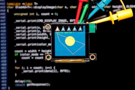
Ce programme va afficher l'image ci-dessous :
Le code source commenté est affiché en seconde partie de ce billet.
Plus d'informations :
Voici les étapes à suivre pour tester cette bibliothèque :
- Décompresser l'archive dans le dossier libraries
- Ouvrez l'environnement de développement Arduino
- Dans le menu Fichier > Exemples, il doit y avoir un menu Oled4D > Example > Demo, cliquez dessus pour l'ouvrir
- Compilez et chargez la cible
Voici une partie du code source (la déclaration de data_image à été tronquée volontairement), l'exemple va afficher un écran bleu, affiche un cercle jaune, 1 tux, réalise 4 copier / coller de l'image du tux, affiche du texte « Hello world ! » puis créé un polygone.
/*  Oled4d
    Programme d'exemple pour interface Arduino / Écran Oled de 4DSystems
 */

#define RED     RGB(255, 0, 0)
#define GREEN   RGB(0, 255, 0)
#define BLUE    RGB(0, 0, 255)
#define YELLOW  RGB(255, 255, 0)
#define WHITE   RGB(255, 255, 255)
#define BLACK   RGB(0, 0, 0)

#define SMALL   FONT_5X7
#define MEDIUM  FONT_8X8
#define BIG     FONT_8X12

#include <NewSoftSerial.h>
#include <HardwareSerial.h>
extern HardwareSerial Serial;
#include <Oled4d.h>

NewSoftSerial serial(2, 3);

// count : 1152
#define  DATA_IMG_WIDTH   24
#define  DATA_IMG_HEIGHT  24
char data_image[] = {
    0x0, 0x0, 0x0, 0x0, 0x0, 0x0, 0x0, 0x0, 0x0, 0x0, 0x0, 0x0, 0x0, 0x0, 0x0, 0x0,
    0xc6, 0xc6, 0xff, 0xff, 0xff, 0xff, 0xff, 0xff, 0xff, 0xff, 0xff, 0xff, 0xff, 0xff, 0xbe, 0xbe,
    [...]
    0x0, 0x0, 0x0, 0x0, 0x0, 0x0, 0x0, 0x0, 0x0, 0x0, 0x0, 0x0, 0x0, 0x0, 0x0, 0x0,
    0x0, 0x0, 0x0, 0x0, 0x0, 0x0, 0x0, 0x0, 0x0, 0x0, 0x0, 0x0, 0x0, 0x0, 0x0, 0x0,
};

void setup()
{
    Serial.begin(9600);

    // Mode série
    pinMode(2, INPUT);
    pinMode(3, OUTPUT);

    // Configuration de l'interface série logicielle
    serial.begin(9600);
}

void loop()
{
    // Créer l'objet en interface série logiciel
    Oled4dSoft oled = Oled4dSoft(serial, 8);

    // Pour utiliser l'uart « hardware », procéder ainsi :
    //Oled4dHard oled = Oled4dHard(Serial, OLED_RESET_PIN);

    // Initialise l'écran
    oled.init();

    // Efface l'écran
    oled.clear();

    // Fond d'écran bleu
    oled.setBG(RGB(0, 0, 128));

    // Dessine un cercle
    oled.drawCircle(64, 64, 20, RGB(255, 255, 0));

    // Affiche l'image
    oled.displayImage(0, 0, DATA_IMG_WIDTH, DATA_IMG_HEIGHT, COLORMODE_65K, data_image);

    // Copier / coller de l'image 5 fois
    for (int i = 1; i < 5; i++) {
        oled.screenCopyPaste(0, 0, i * DATA_IMG_WIDTH, 0, DATA_IMG_WIDTH, DATA_IMG_HEIGHT);
    }

    // Affiche du texte
    oled.drawText(1, 3, SMALL, GREEN, "Hello world !");

    // Dessine un polygone
    char array[] = { 10, 32, 20, 64, 76, 120, 127, 64 };
    oled.drawPolygon(sizeof(array) / 2, array, RGB(255, 128, 0));

    while (1);
}
Voilà, je pense que le code est assez explicite, en cas de souci, n'oubliez pas le forum d'aide.


